
Burnaby Association of Marine Modellers
This is the build history of the BAMM Marine Services dredging crane and barge.
A build in ten sections by Kobus.


Introduction:
Normally I have several projects in the pipeline. It is usually a matter of choosing one to build through the winter.
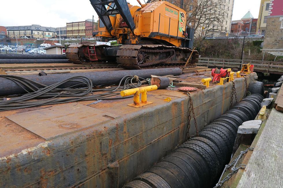
We were visiting our youngest son in Victoria when I saw a crawler crane on a barge, equipped with spuds, working in the harbour. Several photos and a fair amount of research convinced me that I should build a working model of something like this.
Some of the photos taken at the Victoria harbour:


Section 1: The crane had to be built first. If it was not satisfactory, the rest of the project would not make sense.
Using dimensional information on the internet, I could do a layout at 1/24th scale of the crane.
An internet search revealed that there are radio-controlled toy army tanks at 1/24th scale and that spare parts were available. The crawler crane had to have working tracks, but the toy tanks’ tracks were too long. However, I ordered some spare 1/24th scale wheels and a set of replacement tracks.
The photos show the build of the crane chassis, tank steering motor/gearbox installation using a R/C boat speed controller that included a mixer for 2 motors.
The tracks were cut and joined to suit the scale crane drive-train.


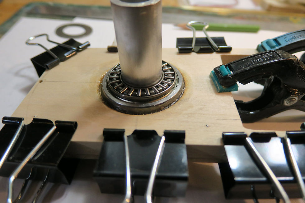
Section 2: Next came the design of the rotating cabin and crane base. I had to have a solid base for this, so I opted for a shaft with a bearing embedded in the crane chassis with a load carrying surface and roller bearing between the cabin floor and the crane chassis. It had to be quite level throughout the 360 rotation, and it had to counter the bending loads imposed by the weight of the crane arm and whatever is being hoisted up. This dictated that the shaft had to be a press fit into the bearing.


Section 3: The electronics/electrical wiring and connections had to be finalized. There would be 4 channels for the crane. Cabin rotation, Boom lift/lower, and two drums with cables for operating a Grapple or Clamshell bucket jaws. The barge would have two drive motors with throttle and tank steering plus rudder and one channel to control the crane tracks forward and aft. This meant that I had two speed controllers/mixers for the barge and crane. The moveable spuds would have a single transmitter/controller & receiver. This arrangement was laid out to determine the wiring, switching sequence and tested


Section 4: The base of the cabin had to be lined up exactly meshing the gear teeth of the of the cabin drive motor with the gear ring on the chassis. The two parts were aligned and clamped together with a small space between the cabin floor hole and the shaft. The gaps were filled with 5 minute epoxy. Once it was all set, the rotation gear mesh and stability of the shaft/bearing could be tested.


Section 5: Using some basic Newtonian laws of forces in cables and pulleys, I concluded that if the crane will at worst have to lift 1 Kg, the lattice structure of the crane boom I had in mind, would be strong enough and that the Injora 35Kg/cm continuous rotation sail winches would be more than good enough. Using the servo’s dimensions, pulley diameters and crane boom attachment points, I could lay out the plan view of the crane floor. Then the 1/24th scale structure for the crane boom lifting/lowering mechanism could be fitted. The scale operator’s cabin was drawn and the balance weights at the back could be drawn. The lattice boom attachment points were installed.


Section 6: The tricky part was next. To have sufficient strength at scale size, the lattice boom had to be built using 1mm and 3mm brass tubing with some 1mm brass sheet parts where required. Since the tubing is thin and would expand quickly when heated, I built some soldering jigs to hold the parts in place while flame soldering. The trick for this kind of construction is to use 3 (or more) types of solder, each with a melting point lower than the next. The first joints are soldered by a high setting on the butane soldering flame, which heats the part up very quickly but also only locally and using the solder with the higher melting point. Then the next joints are soldered with a lower melting point solder etc. The crane boom was made in 3 parts, simulating the real machine, so that additional extensions can be bolted in place. This required exact positioning of the four attachment points of each section. The boom was assembled and attached to the crane floor. All the rigging was done with thin cables and 12mm ball bearing pulleys on 3mm shafts. The whole system was tested.


Section 7: Evergreen plastic sheet and brass tubing/sheet was used to complete the crane body. I made the roof sections removeable so that I can get to the working parts if needed. The ballast weight section at the back was made out of black plastic sheet, filled with 500g of lead-shot and the battery was installed too. The cabin was made with window frames, control panel, seat and 1/24th scale operator.


Section 8: The crane was disassembled and masked for painting. The chassis, drive motor/gearbox assembly was sprayed matt black, then dry brushed with metallic and rust colours to simulate a used machine. The tracks were disassembled, sprayed a metallic steel colour and dry brushed to simulate rusty dirty tracks. Several airbrush coats of white and yellow for the body. Aluminium window frames sprayed and hand painted control panel and interior of the cabin as well as the operator. The final assembly of the body was done, opening of doors and working door handles tested.


Section 9: I looked at all the possible methods of hoisting and other attachments that are normally used by these cranes on a barge. By looking at the diagrams and photos of full-size equipment, various pulley combinations, a Clam-shell Bucket and Mechanical Grapple were designed and built.


Section 10: The crane was completely assembled and tested with various attachments or hoisting pulley combinations. It drives smoothly forwards and backwards on its tracks, steers well and the crane boom responds well to transmitter inputs. It takes some practice to work the Clam-shell and Grapple because the two cable servos need a series of inputs to lower the Clam-shell or Grapple, open it up, grasp the target, close the jaws and the hoist its load up.

